MH2501SC / MH2511SC
应用手册
概述/特点
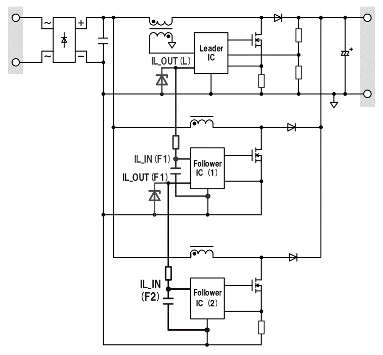
MH2501SC (“leader IC” hereinafter) and MH2511SC (“follower IC” hereinafter) comprise ICs for a current-critical interleaved PFC circuit.
Interleaving with leader and follower ICs ensures low noise and high efficiency, which are characteristics of current-critical PFCs, even in high power regions. One-phase PFC can be configured using just the leader IC.
1. High efficiency and low noise via leader-follower interleaved critical current mode.
2. Two or greater phase interleaving achieved by connecting follower ICs in parallel.
3. One-phase PFC configurable using just the leader IC.
4. Support for wide range of input voltages with guaranteed VCC withstand voltage of 26V.
5. Variety of protective functions.
overvoltage protection, overcurrent protection, feedback open/short protection, and output diode short protection (latch stop)
应用手册目录
1. Outline
1.1 Features
1.2 Block diagram
1.3 Pin arrangement diagram
1.4 Pin function list
2. Operating principles
2.1 Operating principles of current-critical PFC with ON range control
2.2 Zero current detection
2.3 Interleaving
2.4 Startup and shutdown sequences
2.5 Output voltage control
2.6 Phase compensation
2.7 Gate driver
2.8 Protection functions
2.8.1 Overcurrent protection
2.8.2 Output overvoltage protection (OVP)
2.8.3 Low input voltage protection and FB pin open/short protection
2.8.4 Output diode short protection
2.8.5 VCC pin undervoltage protection (UVLO)
2.8.6 Thermal shutdown
2.9 Application circuit
2.9.1 Follower stop protection
2.9.2 Remote ON/OFF
2.9.3 Switching the number of phases
2.10 Example of operation waveforms
3. Circuit example
3.1 Typical circuit diagram
4. Determining peripheral circuit constants
4.1 Selecting choke coils
4.2 Selecting the MOSFET
4.3 Selecting an output diode
4.4 Selecting a bypass diode
4.5 Adjusting constants for components around Z/C pin
4.6 Adjusting phase compensation
4.7 Adjusting the output voltage
4.8 Adjusting the overcurrent protection point
4.9 Selecting the output capacitor
4.10 Selecting the VCC pin capacitor
4.11 LATCH pin
4.12 TIMER pin
5. Precautions for protective functions
6. Precautions for pattern layouts
6.1 Wiring for main current routes
6.2 GND wiring
6.3 Wiring of components around MOSFET
6.4 Wiring of IC peripheral components
6.5 Pattern layout example
6.5.1 Side A
6.5.2 Side B
电路示例
| 应用手册免责声明 |
|
从本网站下载应用手册前,请仔细阅读以下免责声明,只有在同意的情况下,请点击"同意"按钮。 |
|