MV1002SC
应用手册
概述/特点
The MV1002SC is an LED driver IC that uses an external power supply and can consist solely of low-voltage pins. Omitting the auxiliary winding enables a single power supply configuration, and quasi-resonant operation in critical conduction mode raises efficiency and lowers noise.
In general critical conduction mode, the switching frequency increases when the dimming ratio decreases. This increases switching losses and imposes limitations on the lowest dimming ratios, disadvantageously. When the dimming ratio decreases, the MV1002SC automatically switches from critical conduction mode to discontinuous conduction mode. This prevents the switching frequency increasing, reduces switching losses, and achieves smooth and deep dimming free of flickering.
1. Allows quasi-resonant operation without auxiliary winding.
2. Quasi-resonant operation in critical conduction mode helps achieve low input change, raises efficiency, and lowers noise.
3. Off-time modulation enables deep dimming (1% or less).
4. Allows PWM dimming input and linear dimming input.
5. Allows LED open-circuit protection using auxiliary winding.
6. Features built-in thermal shutdown, UVLO, and LED short-circuit protection.
7. Allows configuration solely of low voltage pins using an external start-up circuit.
应用手册目录
1. Overview
1.1 Features
1.2 Block diagram
1.3 Pin assignment
1.4 Pin functions
2. Explanation of basic operations
2.1 Starting sequence
3. Component selection procedure and calculation method
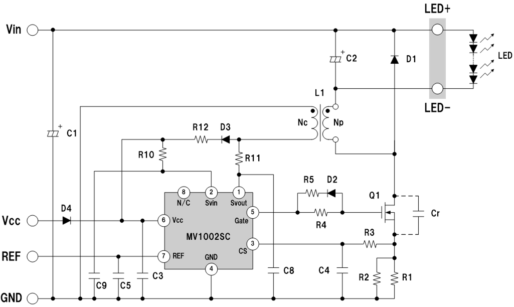
3.1 Basic circuit configuration
3.2 Component selection
3.2.1 MOSFET (Q1)
3.2.2 Fly-wheel diode (D1)
3.2.3 Current detection resistor (R1 and R2)
3.2.4 Inductor (L1)
3.2.5 Gate drive circuit (R4, R9, and D2)
3.2.6 Resistors for Svin and Svout pins(R5, R6, R7 and R8)
3.2.7 CS pin filter (R3 and C4)
3.2.8 Vcc pin smoothing capacitor (C3)
3.2.9 REF pin capacitor (C5)
3.2.10 Svin pin capacitor (C9)
3.2.11 Resonant capacitor (Cr)
3.2.12 Input capacitor (C1) and Output capacitor (C2)
3.2.13 Svout pin capacitor (C8)
3.3 Winding voltage supply
3.3.1 Configuration of a winding voltage supply
3.3.2 Selecting the auxiliary winding (Nc)
3.3.3 Selecting the auxiliary winding rectifier diode (D3)
3.3.4 LED open-circuit protection using auxiliary winding
4. Cautions on pattern designing
4.1 Cautions
4.2 PCB pattern example
5. Dimming characteristics
5.1 Operation in each mode
5.1.1 [A] Frequency modulation region
5.1.2 [B] Off-time modulation region
5.1.3 [C] Minimum dimming region
5.2 PWM dimming
5.2.1 PWM dimming in 100% and minimum dimming ratio regions
5.2.2 Combination of linear dimming and PWM dimming
5.3 Dimming circuit
5.3.1 Example of dimming circuit smoothing PWM signal
6. Operations in abnormal situations
6.1 LED open-circuit
6.2 LED short-circuit
6.3 Abnormal heat buildup
6.4 CS pin open-circuit
6.5 CS-GND short-circuit
6.6 Current detection resistor open-circuit
6.7 Current detection resistor short-circuit
7. Standard circuit example
7.1 Power supply specification and circuit diagram
7.2 Power supply characteristics
7.3 Example of operation waveform
电路示例
| 应用手册免责声明 |
|
从本网站下载应用手册前,请仔细阅读以下免责声明,只有在同意的情况下,请点击"同意"按钮。 |
|