MV2002SG / MV2052SG
应用手册
概述/特点
The MV2002SG and MV2052SG are two-channel LED driver ICs that can be configured using just low-voltage pins via an external power supply.
One control IC is used to control the current for two channels, providing excellent relative current accuracy and enabling consistent color reproduction.
Current critical control is possible through quasi-resonant operation without auxiliary windings, enabling high efficiency and low noise using a simple power supply configuration.
With conventional current critical control, the switching frequency increases as the dimming rate decreases, resulting in drawbacks such as increased switching losses and limitations on minimum dimming values. The MV2002SG and MV2052SG, however, automatically switch from current critical operation to current discontinuous operation with the decrease in dimming rate, and this suppresses the increase in switching frequency, reducing switching losses and enabling smooth flicker-free deep dimming.
Oscillation on/off control is also possible by adjusting the RC pin voltage or dimming pin voltage (REF1, REF2) above or below a threshold voltage.
The ICs incorporate a power supply for an external microprocessor to supply a microprocessor voltage without three-pin regulators or similar devices.
(MV2002SG: 3.3V, MV2052SG: 5V)
1. Excellent relative current accuracy for each channel provides consistent color temperature when dimming.
2. Allows quasi-resonant operation without auxiliary windings.
3. Quasi-resonant operation using current critical control provides high efficiency and low noise with minimal input fluctuation.
4. Allows deep dimming using off-time modulation (not exceeding 1 %).
5. Allows PWM dimming and linear dimming.
6. Allows oscillation on/off control using the RC pin and dimming pin (REF1, REF2).
(Oscillation starts when VRC > Vth_RC_st and VREF > Vth_REF_st.)
7. Incorporates built-in power supply for external microprocessor (3.3V for MV2002SG, 5V for MV2052SG).
8. Outputs an alarm signal on detecting abnormal operation.
9. Allows LED open protection using the auxiliary windings.
10. Incorporates overheat protection and UVLO/LED short-circuit protection functions.
11. Allows configuration using only low-voltage pins via use of external startup circuit.
应用手册目录
1. Overview
1.1 Features
1.2 Block diagrams
1.3 Pin assignment diagram
1.4 Pin function list
2. Basic Operations
2.1 Startup sequence
2.2 Regulator function
2.3 Remote control (RC) function
2.4 Alarm signal output function
3. Component Selection Procedure and Calculation Method
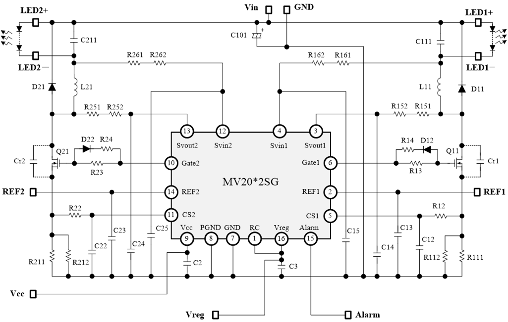
3.1 Basic circuit configuration
3.2 Component selection
3.2.1 MOSFET selection
3.2.2 Regenerative diode selection
3.2.3 Current detection resistor selection
3.2.4 Inductor selection
3.2.5 Gate drive circuit selection
3.2.6 Svin and Svout pin resistance selection
3.2.7 CS pin filter selection
3.2.8 Vcc pin smoothing capacitor selection
3.2.9 REF pin capacitor selection
3.2.10 Svin pin capacitor selection
3.2.11 Resonant capacitor selection
3.2.12 Input capacitor and output capacitor selection
3.2.13 Svout pin capacitor selection
3.3 Types using auxiliary windings
3.3.1 Circuit configuration for types using auxiliary windings
3.3.2 Auxiliary winding selection
3.3.3 Auxiliary winding rectifier diode selection
3.3.4 LED open protection using auxiliary windings
4. Pattern Design Precautions
4.1 Precautions
4.2 PCB pattern example
5. Dimming Characteristics
5.1 Mode operations
5.1.1 [A] Frequency modulation region
5.1.2 [B] Off-time modulation region
5.1.3 [C] Oscillation stop region
5.2 PWM dimming
5.2.1 PWM dimming in 100 % and oscillation stop regions
5.2.2 Combination of linear dimming and PWM dimming
5.3 Dimming circuit
5.3.1 Example of dimming circuit for smoothing PWM signal
6. Operations in Abnormal Situations
6.1 LED open-circuit
6.2 LED short-circuit
6.3 Overheating
6.4 CS pin open-circuit
6.5 Short-circuit between CS and GND pins
6.6 Current detection resistor open-circuit
6.7 Current detection resistor short-circuit
7. Standard Circuit Example
7.1 Power supply specifications and circuit diagram
7.2 Power supply characteristics
7.3 Operation waveform examples
电路示例
| 应用手册免责声明 |
|
从本网站下载应用手册前,请仔细阅读以下免责声明,只有在同意的情况下,请点击"同意"按钮。 |
|